The purpose of being able to move a servo from inside Autodesk Maya is to make the process of animating an animatronic faster, easier, and more intuitive. Currently, the servos are being connected to simple 3D cubes. This might be fast, but definitely not intuitive since the cubes don't give a visual representation of the movement, and therefore animating becomes confusing.
To make animating animatronics more intuitive, a visual representation of the movement can be used. Since the animatronic I'm using is 3D printed, I have access to the models as a .STL file. STL (Standard Triangle Language) is the industry standard file type for 3D Printing. It uses a series of triangles to represent the surfaces of a solid model.[1] One of the characteristics the .STL model has is that the original wireframe is converted to a triangulated version. This isn't very pretty, but for this purpose, it isn't a problem.
Just the eye or the whole build?
As a visual representation for rotating the servos, using just the eyeball and its eyelid are enough.
In the following example, the eye and its eyelid are used as a visual representation. The eyeball is following a locator using an aim constraint. An aim constraint lets you constrain the orientation of an object so that the object points to other objects.[2] In this case, the eyeball is pointing to the pivot point of the locator. In this virtual setup, the locator isn't limited to a certain position relative to the eye. The locator can be placed anywhere and the eyeball will follow. This setup can be used with Servo Tools for Maya, but we would run into two major issues. The first being that the virtual setup doesn't keep in mind real-world constraints and the second issue is that the movement of the real eye doesn't match the virtual eye.
Figure 1. Eye rig (Own work)
The first issue can be fixed by limiting how far the eyeball can rotate or limiting where you can place the locator in relation to the eyeball. The second issue, however, isn't easily fixed.
I hypothesized that the movement of the real version of the eye won't match the movement of the virtual eye when it's directly rotated in Autodesk Maya. The rotation that the servo is making is not the same rotation as the eye is making. When you rotate the eye directly, you miss the difference in transmission movement that the mechanical parts are making.
To put this to the test the locator was positioned so that the eyeball rotated 45 degrees away from the center. This is done by snapping the locator on the grid. (see fig1.)

Figure 2. Eyeball rotated 45 degrees away from the center (Own work)
If we take a look at the real setup we can see that when we rotate the virtual eyeball 45 degrees away, the real eyeball doesn't rotate the same angle (see Fig2.)

Figure 3. Servo reaction to input: 45 (Own work)
Assuming the pivot point of the eyeball is positioned in the middle of the two protractor triangles, a line can be drawn from the center through the middle of the pupil. Reading the results we can see that the eyeball actually rotated around 26 degrees. However, this number should be taken with a grain of salt since our measuring setup is far from accurate. It does, however, prove the point that the rotation of the eyeball and the servo aren't linear.
New questions arise.
How accurate will this setup be when the whole build is used?
How accurate does it need to be?
Does it actually matter?
Building a virtual copy
In this example, all of the 3D printed models are used to recreate the build-in Autodesk Maya. The .STL files don't "snap" together in the scene by default, they have to be rotated and moved manually. The pivot point of the models also has to be repositioned in order to rotate correctly around the axis.
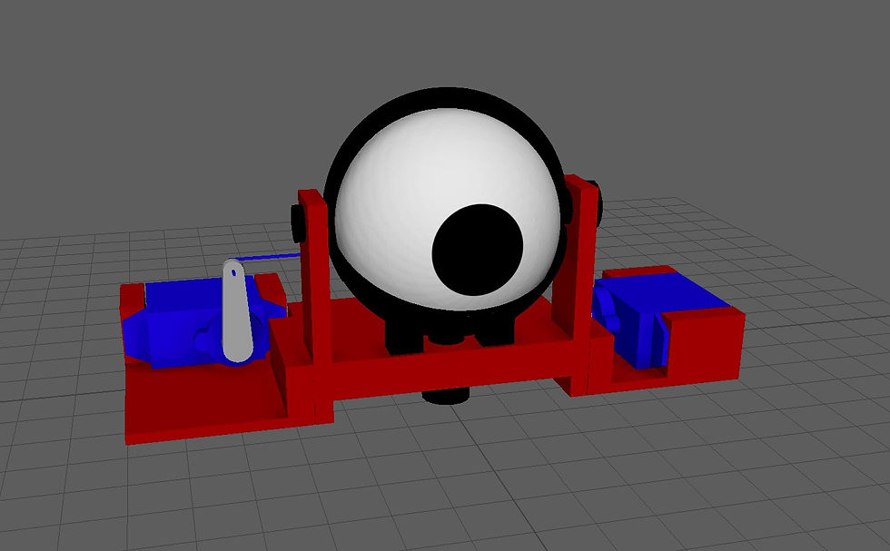
Figure 4. Virtual replica of eyeball prototype (Own work)
Once that's done the rigging process can begin. Rigging refers to the process of creating the bone structure of a 3D model. This bone structure is used to manipulate the 3D model like a puppet for animation. Pretty much anything can be rigged. A spaceship, a soldier, a galaxy, a door, it doesn’t make any difference what the object is. Adding bones will allow any object to be animated freely. [3]
First, we are going to make a connection between the left servo and the eyeball. For the rotation of the eyeball, many components need to be linked. Servo horn -> paperclip -> servo control arm -> eyeball

Figure 5. The backside of eyeball prototype (Own work)
A joint chain is created using 2 joints. The root joint is placed on the pivot point of the horn and the second joint is placed in the center of the paperclip "hole". The joints are orient-constraint to a NURB controller. The NURB controller is now used to rotate the horn. The paperclip model is parented under a locator. This locator is point-constrained to the second joint. Wherever the top joint goes, the locator goes as well while maintaining offset.
Figure 6. Virtual servo rigged (Own work)
A second locator is placed at the end of the paperclip, parented under the first locator. The second locator makes the exact same movement as the first while maintaining offset. A third locator is point-constrained to the second locator, but only on the X-axis. Because it is only constrained on the X-axis, it doesn't follow the up and down movement of the paperclip. Now the last locator is made and placed on the pivot point of the eyeball. This last locator is aim constrained towards the third locator. This means that the aim constrained locator stays in place, but follows the rotation of the third locator. The eyeball model is parented under the locator and therefore rotates the same as the aim constrained locator. To finish this part of the rig, a limit is set on how far the horn can be rotated by using Maya's "Limit Information" attribute found in the attribute editor. This limitation is set to limit the rotation of the servo to mimic real-life constraints since it shouldn't be able to rotate further once it hits the plastic servo bracket.
Figure 7. Rigged eyeball prototype moving real servos (Own work)
The rigging setup described above is not the only way or even the best way to rig a setup like this, but it results in a close resemblance of the movement the real setup makes. It's important to keep in mind that the movement is not 100% correct since we aren't keeping in mind that the paperclip is bending a little bit in the real setup.
Comments